Hi, I’m Albert
This is where I post about projects and leanings from the past and present in the hope that someone else (my future self included) will find them useful. You can contact me on social media, or email at “mail” on this domain.
-
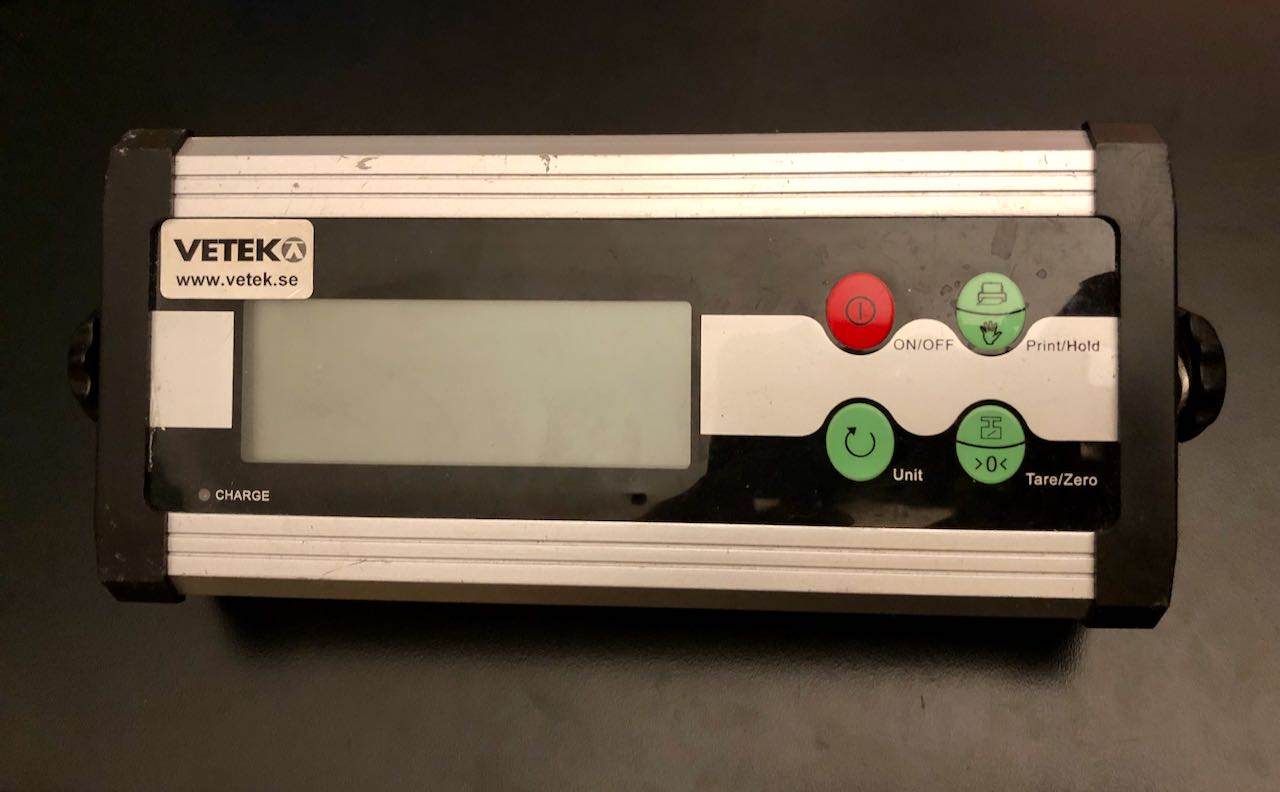
Vetek TCS-D Scale Repair
#
I was asked to have a look at this digital scale. The LED in the bottom left corner came on green when power was connected, but nothing happened when the ON/OFF button was pressed. After some measuring, I found there was no 5 V rail. The power to the two 5 V regulators is enabled […]
-
DIY Display Dimmer: Physical Brightness Control for Monitors

My USB-C port replicator does not pass on brightness commands to my external monitors. The idea of a hardware solution was floating around in the back of my mind for a while. Until my friend made exactly this. I decided, if he was no longer fiddling with the screen’s built-in menu, neither was I! HDMI […]
-
Garmin Forerunner 210 Strap Repair

I have a problem with e-waste. For example, I can’t stand throwing away this perfectly working GPS watch simply because the strap is not replaceable. Sadly, this seems to be a common problem with the Garmin Forerunner 210. As far as I can tell, spare parts were never available for this model. I bet quite […]
-
Getting Started with CH32V003 Firmware in Rust

#
I have been working on a small project using the WCH CH32V003 and thought it would be fun to make a version of the firmware for it in Rust. I started by having a look around for hardware support and getting started guides. As it turns out, there is a HAL and hardware support by […]
-
Proxmox: Bridge port enp1s0 does not exist
I was adding a new NVMe drive to a previously unused slot on my little home server running Proxmox. After putting it back together, my services, like Home Assistant and Pihole, never came back online. Running systemctl status networking, I could see the error message: Long story short: Adding a new drive changed the enumeration […]
-
Installing TivaWare on Mac, in 2024
I recently dug up my old autonomous car project based on a Texas Instruments Tiva C EK-TM4C123GXL Launchpad. The process of getting it up and running on a new(er) mac was fairly straightforward. First, I installed Code Composer Studio: TivaWare, the SDK for Tiva C is still available for download at https://www.ti.com/tool/SW-TM4C. Unfortunately, the installer […]
-
IKEA Floalt Light Panel Repair
Finally, I have come full circle on this repair that started five years ago when one of my IKEA FLOALT light panels (L1529, 60×60 cm) suddenly started flickering. It has long been gathering dust, but I finally dug up this old Reddit post with a suggested repair that I had bookmarked: So credit where credit […]
-
Bringing Back the Stellaris Evalbot
TLDR; https://github.com/albertskog/stellaris-evalbot-fw In my pile of old development kits is this little robot from Texas Instruments. The microcontroller on it is the LM3S9B92, an old (and, I seem to recall, fairly buggy) ARM Cortex-M3 chip. It must have gathered dust for around ten years at this point, but I did not want to throw it […]